Belts and Chain Drives - Machine
Wednesday, March 8, 2017
3 Comments

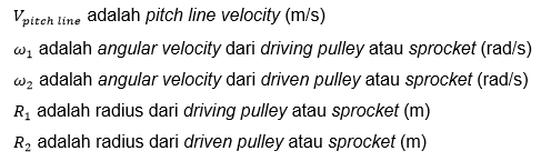
Belt and chain (chain drives) are used to transmit power from one power mover towards other movers. Belt is a flexible power mover components and fitted tightly on one set of pulley while the chain of paired sprocket on a set. Speed ratio between the driving (driving) and the driven shaft depends on of the diameter of the pulley or sprocket ratio as the following equation:

Belt and chain can transmit power (power) between the axle with a distance far enough so it gives leeway for designers in designing the layout engine. If compared with gears (gear), belt and chain are also relatively cheaper.
Belt drives are generally used if the playback speed range between 10 and 60 m/s while the chain (chain drives) are used to lower speeds and has a higher torque than belts. Some excess belt drives compared to the chain and gears are easy to install, does not require a lot of maintenance, have high reliability, may be used on non-movers are parallel and high transmission speed. Lack of belt drives is channeling the energy capacity is limited. Belt is also less compacted than gears and chains as well as susceptible to broken due to the influence of such an environment contaminated by lubricants. Additionally, vibration and shock loads can damage the belt.
Chains are usually more compacter than as belt as well as provide power and speed capacity ratio better than belt. The chain is also more powerful than the belt drives due to the use of steel to make. Regarding the price cheaper than chain gears and the price is competitive when compared to belt drives. The shortcomings of the chain is a finite ratio and speed connection regarding security. The chain can be disconnected and detached from the sprocket with style and high-speed. Protector (guard) should be provided for the chain and belt to prevent breakage of chain or belt and prevent the occurrence of accidents.
1. Belt Drives.
There are many types of belt configurations like flat (flat), spherical (round), V, wedge and synchronous belt drives with its character of each. Cross-section of the type of belt is shown in Figure 2. Most belt made of rubber or polymer-based materials.


Flat belts have high strength, can be used for a large speed ratios (8:1), the cost of the pulley is cheap, generates noise (low noise level) and well in absorbing vibration couplings. These belts are made of many layers where each layer has special functions. The use of the belt as shown in the manufacturing tools, saw mills, textile machinery, food processing machines, multiple spindle drives, pumps, and compressors.
This type of belt which is most widely used in the industry and the automotive world is V belt or wedge belt. In automotive V belt is used to connect the crankshaft (crankshaft) and various other components such as the alternator, water pump (water pump) and a cooling fan. V belt is also used for a variety of purposes ranging from household equipment at up to heavy-duty rolling machine.
Synchronous belt or timing belt also named have teeth that are associated with teeth on the pulley. This has advantages i.e. the occurrence of angular synchronization between the driving and driven shafts and ensures a constant speed ratio. Comparison of different types of belt shown in Table 6.1.

The procedure for selecting the belt is shown in Figure 4.

1.1 Wedge Belt Selection
The procedure for choosing a belt with regard to power speed rating is as follows:
Determine operational conditions
This includes operational conditions determine nominal power (power) that is transmitted, determine the playback speed (rotational speed) from the shaft, space or room is available, the layout and other considerations include the condition of the environment.
Determine service factor.
Service factor used to down-rate capability of the belt in the transmit power (power) who have written the manufacturer belt and count them when it should be used on the actual application. Service factor of the belt is shown in table 2.
Calculate the design power.
The design power is the product of the nominal power and service factor.
Determine the type of belt.
As a guide to determine the right type of belt can refer to figure 5.
Pick belt.
Use the manufacturer's rating chart, select a belt specifically to suit the design power and speed (speed).
Determine the diameter of the pulley.
Pulley basically already have standard size. Select the pulley with the size of the smallest where the speed ratio is still acceptable.
Set center distance.
Center distance depending on the application. As a general guide, center distance must be greater than the diameter of the pulley.
Determine the length of the belt.
Belt is usually made with a length that a already have standard so some iteration must be performed to get satisfactory results.
Use power correction factor.
This is done to compensate for the speed ratio and belt geometry and available on the belt manufacturer design guides.
Determine the allowable power per belt (or per belt width for flat belts)
This is a function of the dimensions of a belt and informed on the manufacturer design guides.
Determine the amount of belt.
The number of belt is obtained by dividing the power design with allowable power per belt and rounded to the nearest integer becomes.
Example 1
Select wedge belt and specify the diameter of the pulley to a compressor which is driven by a two-cylinder diesel engine with power 28 kW. Speed dial is engine 1500 rpm and the speed of the rotary compressor is 950 rpm. The proposed distance between the engine and the compressor are 1.5 m. System is planned to be used less than 10 hours per day.
Solutions
The speed ratio is 1500/950 = 1.58
From table 2 indicated that for “heavy starts,” “heavy duty,” and the hours of operation for less than 10 hours per day, the service factor is 1.4.


From Figure 5, the combination of 39.2 kW power and speed dial 1500 rpm it was found that these values are in the areas of SPB belt drives. The combination of power and speed dial be also in the area of the SPA but the distance is near so selected here is SPB.


From table 3 to design power 39.2 kW and driving shafts speed 1500 rpm, minimum diameter of 160 mm pulley suitable for selected.
From table 4 to speed ratio of 1.58 pitch diameter fits D1 = D2 = 224 mm and 355 mm. Center the closest distance that can be selected is a long belt 1,544 mm. is 4000 mm and arc-length correction factor is 1.05.
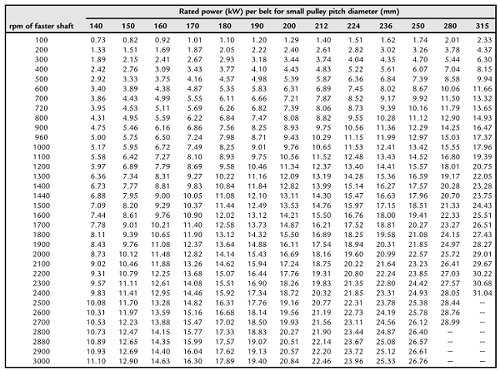
From table 5 rated power per belt for n1 = 1500 rpm and D1 = 224 mm was 15.97 kW/belt.
From table 6 additional power per belt is calculated based on the speed ratio is 1.11 kW.
Corrected value for the power per belt is (15.97 + 1.11) × 1.05 = 17.93 kW/belt.
The total number of belt is (on/17,93) = 2.19.
Example 2
Wedge belt drives required for transmitting 18.5 kW from an electric motor that operates at 1455 rpm. The power is transmitted on a conveyor that operates on a round of 400 rpm. Center the desired distance is 1.4 mm and estimation system usage is 15 hours a day. Choose a belt that is suitable for the system and specify the diameter of the pulley.
Solutions
18.5 kW, n1 = n2 = 1455 rpm, 400 rpm, C ≈ 1.4 mm
Speed ratio = 1455/400 = 3.6375
From table 2, the service factor is 1.1.
Design power = 18.5 × 1.1 = 20.35 kW.
From Figure 5, SPB belt suitable for use.
From table 3 minimum pulley diameter is 112 mm.
From table 4, choose the closest ratio is 3.57, D1 = 224 mm, D2 = 800 mm and C ≈ 1.416 m (SPB4500). Combined arc and belt length correction factor is 1.0.
From table 5, rated power per belt approximately 15.47 kW.
From table 6 additional power per belt is 1.21 kW.
Corrected power per belt is (15.47 + 1.21) = 1.0 × 16.68 kW.
The required amount of belt is 20,35/16,68 = 1.22.
Rounded at the top, using two SPB4500 belts with pulley diameter 800 mm and 224 and center distance 1.416 m.
Source: Belts and Chain Drives
Hi there! Nice material, do keep me posted when you post something like this again! I will visit this blog leaps and bounds for more quality posts like it. Thanks... automotive logistics
ReplyDeleteI should assert barely that its astounding! The blog is informational also always fabricate amazing entitys. best hospital for lasik eye surgery in delhi
ReplyDeleteDiesel engines tend to be louder but more durable. crate motor 350
ReplyDelete